3.3V conversion for CH340 Arduino Nano clone | Home Page |
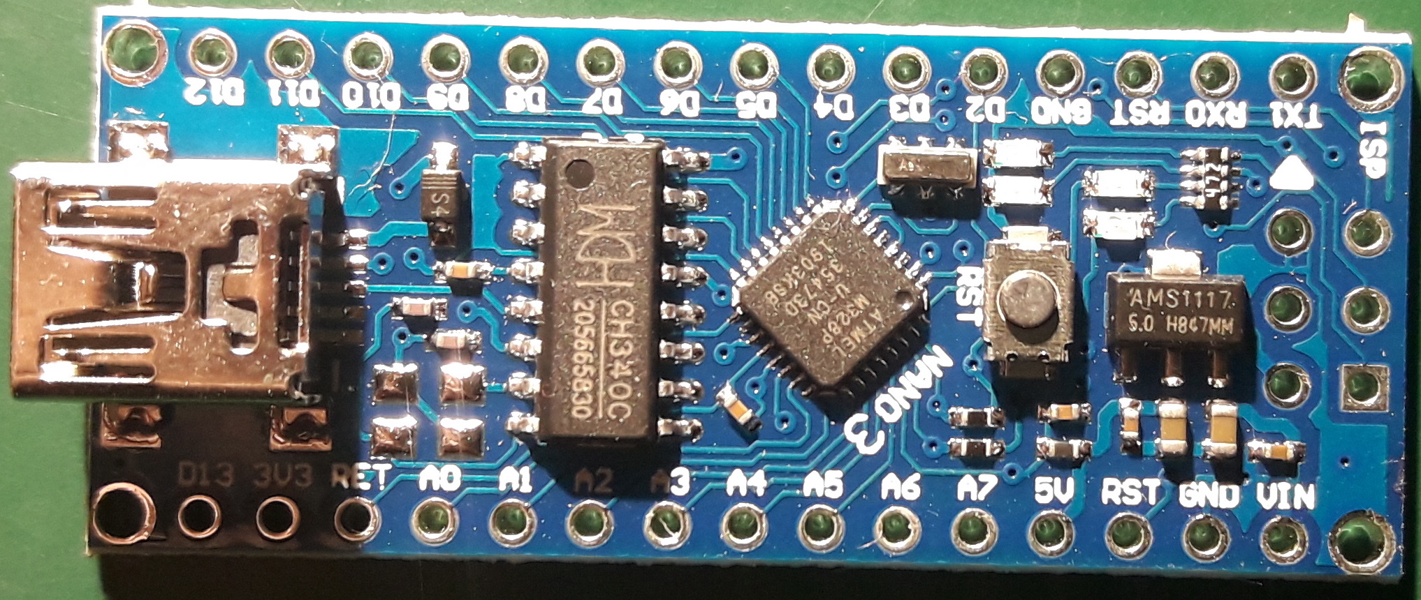
Many peripheral modules I want to use with the Arduino want 3.3V, and I don't want to always have to use level translators. So following some ideas online, I developed my own modification for a common type of Arduino Nano clone shown here. These use a CH340 chip for USB serial I/O. Beware, there is another common clone that has the CH340 mounted on the bottom of the board. I'm sure you could use the same idea, but my instructions are for the type shown here.
Note that 16MHz operation on 3.3V is slightly out of spec for the AVR chip, so although it will work fine in normal use, you might run into trouble at the extremes of the temperature range. But if you need to worry about that, you probably won't be using a Chinese Arduino clone anyhow.
The AMS1117 5V regulator (at right) is not used when you connect to USB, only when you use an external power source on Vin (bottom right corner), so we're going to change it to 3.3V and rewire around it.
First thing, remove that regulator and fit a 3.3V version. The AMS1117 regulator is in a SOT89 package, not the larger SOT323 you find on some boards. I found a 3.3V version here on Aliexpress. The trick with de-soldering this thing is that the tab is connected to the centre pin. If you set your soldering iron a little higher than normal (say 400C), then get a blob of solder on the tip, you can apply the tip sideways across all three pins, and ignore the tab. It will get enough heat for the whole regulator to come off cleanly. Tidy up any residual solder using solder-wick before fitting the new one (solder the tab first this time, then re-heat all three pins with enough solder). Buzz it with a continuity checker to make sure you haven't shorted the regulator pins.
Normally the USB supply is connected to the regulator output (the centre pin and tab) via a Schottky diode, which you can see labelled S4 at the top left of the picture. The diode prevents your Arduino from trying to feed power back via USB into your computer, which might not like that. We've dropped the 5V rail to 3.3V, so that diode has to go, or connecting to USB will pull the Nano up to 4.7V. Unsolder one end and lift it with the soldering iron, then unsolder the other end and it will drop off.
Now, reconnect the 5V from the USB to the input of the regulator, which is the right-most pin (also connected to Vin on the edge of the board). You'll need a small piece of wire, preferably teflon-coated like wire-wrap wire. Strip 2mm at one end and solder it where you removed the diode, on the side near the USB connector (leave the other diode pad unconnected; this will be at 3.3V). Route the wire and strip 2mm at the other end. You can solder it directly to the regulator, or if you already have the row of pins fitted along each side (or won't want to) you can solder it directly to Vin. I used the first option here. Buzz it to check connectivity from the USB power input to Vin.
The CH340 chip has a small internal regulator that makes 3.3V from its power input (top right pin), when it is running on 5V. It's only capable of a few milliamps, but this 3.3V appears at pin 4 (fourth down on the left) and runs to the Nano's 3v3 connector. The chip cannot make its own 3.3V supply when the input is only 3.3V, so we need to connect these two pins. Solder a small piece of bare wire to pin 4, tidy up the end, and slant it across to solder to pin 16 (top right). Buzz it to check connectivity from the 3V3 connector on the edge of the board to the tab of the regulator.
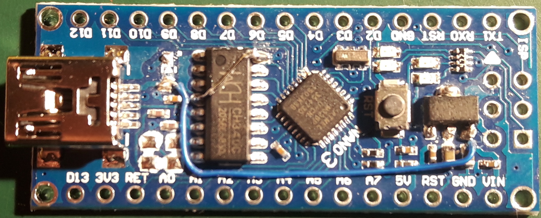
That completes the modification. The Vin external supply is now connected directly to USB, so don't use them both at the same time. The Arduino will run nicely from USB, but all pins (except Vin) will only go to 3.3V. It will also run nicely from any Vin source from 4-18 volts.